Lab Environment Architecture
Device Configuration
Project Details
Logical Architecture Mapping
| Hostname | Device | Operating System | Role | IP Address | VLAN | Description |
|---|---|---|---|---|---|---|
| T-TermSrv | Cisco 2901 Router | IOS 15.7 | Terminal Server / COM Router | 172.16.22.1 | N/A | Terminal Server with Console Connections Into All Other Devices |
| T-Nexus | Cisco Nexus 5548UP | IOS 7.3.13 | Core Switch | 10.26.55.48 | N/A | Core OSPF Backbone Switch |
| T-DellPWR | Dell PowerConnect 8024F | DellOS 5.0.0.4 | Access Switch | 10.0.10.5 | 1,10,20 | OSPF Area 1 Switch to PC3 |
| T-2911-A | Cisco 2911 | IOS 15.7 | VLAN 30, 40 Default Gateway | 10.26.29.11 | 1,30,40 | OSPF Area 2 Defualt Gateway |
| T-ISR-A | Cisco ISR 4331 | IOS 16.12 | Area Border Router | 10.26.43.31 | 1,10,20 | OSPF Area 1 Default Gateway |
| T-ISR-B | Cisco ISR 4331 | IOS 17.9 | GLBP Default Gateway | 10.26.43.32 | 1,10,20 | EIGRP GLBP Default Gateway |
| T-ISR-C | Cisco ISR 4331 | IOS 17.9 | GLBP Default Gateway | 10.26.43.33 | 1,10,20 | EIGRP GLBP Default Gateway |
| T-2901-A | Cisco 2901 Router | IOS 15.7 | VPN Concentrator | 10.26.29.1 | N/A | DMVPN Hub |
| T-2901-B | Cisco 2901 Router | IOS 15.7 | VPN Concentrator | 10.26.29.2 | N/A | DMVPN Spoke & IS-IS Default Gateway |
| T-2901-C | Cisco 2901 Router | IOS 15.7 | VPN Concentrator | 10.26.29.3 | N/A | DMVPN Spoke & EIGRP DHCP Server |
| T-3750-A | Cisco 3750e | IOS 15.2 | Core Switch | 10.26.37.50 | N/A | OSPF Area 2 DHCP Server |
| T-3750-B | Cisco 3750e | IOS 15.2 | Access Switch | 10.0.30.5 | 1,30,40 | OSPF Area 2 Switch to PC4 |
| T-3750-C | Cisco 3750e | IOS 15.0 | Access Switch | 172.16.10.5 | 1,10,20 | EIGRP Switch to PC1 |
| T-3750-D | Cisco 3750e | IOS 15.2 | Access Switch | 192.168.10.5 | 1,10,20 | IS-IS Switch to PC2 |
Network Segmentation
The network was set up to allow for dynamic establishment of site-to-site VPN connections between multiple locations. To do this, locations were set up with routing protocols and VLANs in a mock topology to support a growing business. To support the growing system's infrastructure, four primary Virtual Local Area Networks (VLANs) were established throughout all locations. Not all VLANs were used in all locations. The necessary VLANs for client connectivity were as follows: 10, 20, 30, and 40.
Marketing (VLAN 10)
- Subnets: 10.0.10.0/24, 192.168.10.0/24, 172.16.10.0/24
- Traffic Designation: Blue
- Client Network For the Marketing Departments
Sales (VLAN 20)
- Subnets: 10.0.20.0/24, 192.168.20.0/24, 172.16.20.0/24
- Traffic Designation: Red
- Client Network For the Sales Departments
Accounting (VLAN 30)
- Subnet: 10.0.30.0/24
- Traffic Designation: Green
- Client Network for the Accounting Department
Research & Development (VLAN 40)
- Subnet: 10.0.40.0/24
- Traffic Designation: Yellow
- Client Network for the R&D Department
Physical Infrastructure
- EH-WICs and NIM modules for network expandability
- HWIC-DSU modules for T1 Cable Connections
- Copper SFPs and TwinGig Module for network medium conversion
- Green Async Cable Connections to the console port on all devices
- RJ-45 CAT6 UTP Cables for general connectivity
- MM Fiber Connections for core switching connectivity
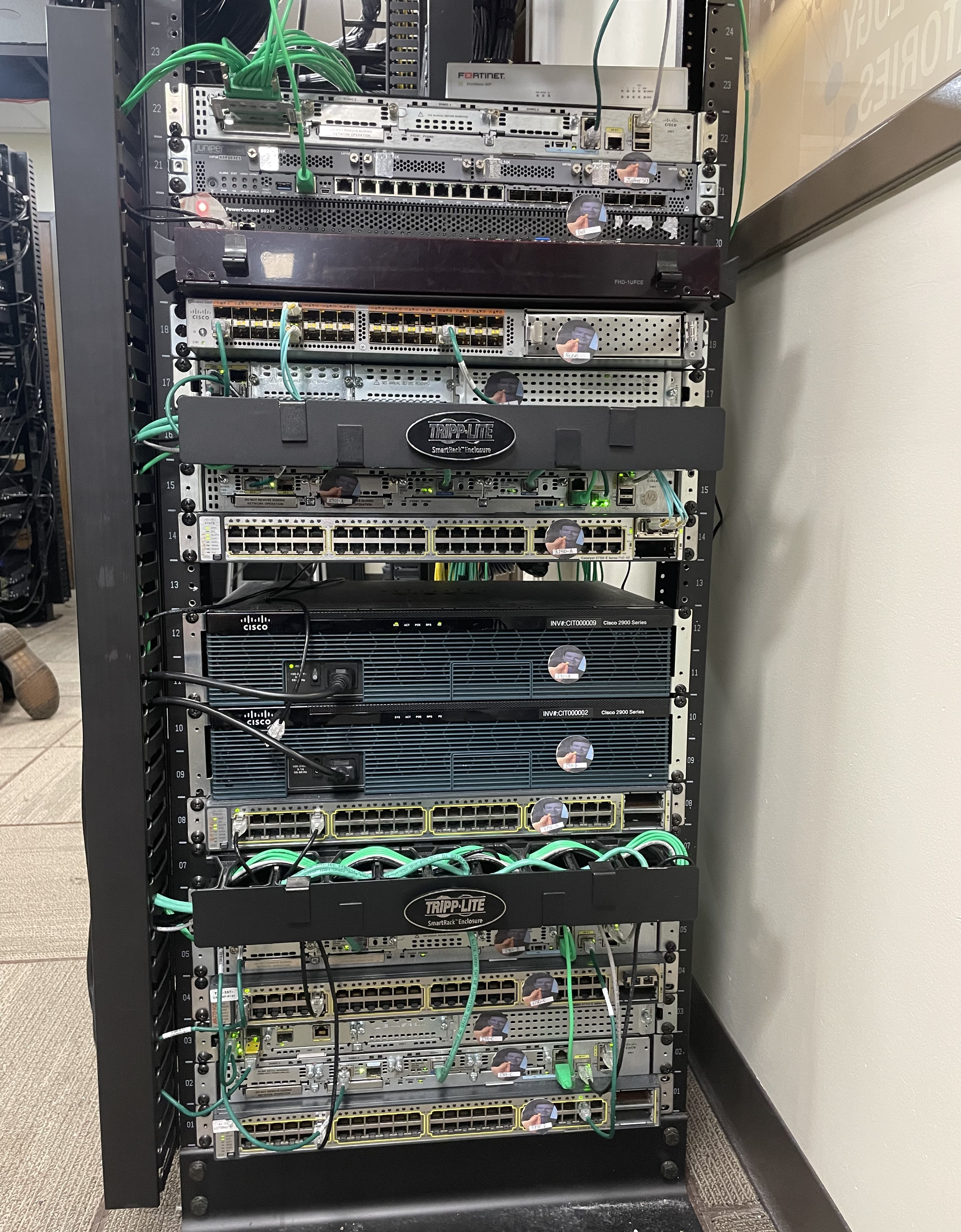
Physical implementation of the network infrastructure
Network Architecture
The setup of the above topology has the following branch locations: Site A (Headquarters), Site B (Branch 1), and Site C (Branch 2).
Site A
Site A was the biggest site and headquarters of this mock topology. Therefore, it was set up as the hub of the DMVPN. Site A consisted of a multi-area OSPF network with areas 0, 1, and 2. Each area was set to represent a different building within a campus topology with area 0 being the backbone area to connect the buildings together. The architecture included a core network architecture of 2 fiber link aggregated layer 3 switches and 4 primary VLANs and subnetworks for client connectivity throughout the architecture. As mentioned above, VLAN 10 was for the marketing department, VLAN 20 for the sales department, VLAN 30 for the accounting department, and VLAN 40 for the research & development division. Finally, a centralized DHCP server for IPv4 and IPv6 was set up on T-3750-A, one of the core switches within the topology.
Site B
Site B was fairly small. It was the smallest of the three sites and consisted of a single router-on-a-stick topology consisting of T-2901-B. The routing protocol IS-IS was used here to connect the routes between the internal and remote sites within the infrastructure. Even though there were only two routes in this topology, if there were ever needs for future expansion, it would make the process more scalable. In the long run it would be more efficient than manually specifying all routes when redistributing to advertise routes into the DMVPN. DHCP services for this site were made on the same router with 4 total pools to accommodate both marketing and sales over IPv4 and IPv6 at the remote site.
Site C
Site C was a medium site compared to both A’s large site and B’s small site. It was a site that utilized 3 routers and one switch to service clients on the network. This site was set up with the internal routing protocol EIGRP as all routed devices within this site were Cisco. Two of the routers, T-ISR-B and T-ISR-C, were set up in a redundant Gateway Load Balancing Protocol (GLBP) pairing to load balance connections across the network in a round-robin fashion. Similarly to site B, vlans for the Marketing and Sales department were established with DHCP pools for both IPv4 and IPv6 on the central edge router of the topology.
Dynamic Multipoint Virtual Private Network
Dynamic Multipoint VPNs (DMVPNs) are a technique of configuring VPNs so that not all sites must be statically configured. One site is primarily configured as a hub with all other sites being configured as spokes. For example in the topology above, site A was configured as a hub with sites B and C being configured as spokes. The configuration uses NHRP to allow spokes to connect to the hub, allowing site A to keep cache records of both sites B and C. Sites B and C are then able to communicate with each other dynamically without the need for a static point-to-point configuration between sites B and C. B can peer and communicate with C and vice versa through site A without decrementing the TTL. Encryption across tunnels is also supported, making DMVPNs a popular way to securely communicate between multiple branch site locations. The DMVPN configuration above was as follows: Site A (T-2901-A) was the hub with sites B (T-2901-B) and C (T-2901-C) being spokes. The DMVPN topology was established for both IPv4 and IPv6 internal networks through a shared tunnel 0 with separate network ids. Internal networks for each site used a different routing protocol with shared tunnel between them using exterior Border Gateway Protocol (eBGP). While EIGRP is more common in tunnels between DMVPN hubs and spokes, I already had EIGRP as the routing protocol for site C and wanted to use BGP to become more familiar with the protocol and its redistribution commands that were still relatively new to me. Through the successful implementation of the DMVPN, I was able to dynamically communicate between remote sites and allow for communication of both IPv4 and IPv6 internal networks across an IPv4 public infrastructure.
Multi-Protocol Label Switching
Finally, an MPLS network connection was established across sites via a mock T1 connection. Instead of T1 lines being routed through phone lines, these connections were directly connected via Serial interfaces on HWIC-1DSU-T1 modules. I constructed two T1 cables and connected them from T-2901-B to T-2901-A and T-2901-C to T-2901-A. These cable connections were to be used as a physical backup connection in the potential failure of the DMVPN connection. The connections were set up with the command “mpls bgp forwarding” to allow the forwarding of MPLS-labeled packets across a BGP session. Routes were then inserted into BGP. Here, the routes came online and populated into the routing table. As I wanted the MPLS connection to be a backup to the DMVPN, I shutdown the two serial interfaces on Cisco T-2901-A which caused the routes for the remote networks to recalculate and use the DMVPN. After this was confirmed to be working correctly, the serial interfaces were brought back online and did not retake priority of the remote networks’ routes. Functionality was working as expected and all services were operational. However, looking back, I do wish I would have looked further into the cause behind this so that whenever the DMVPN was up or came online that it would preempt and take priority from the MPLS connection, instead of me needing to go in and manually change it.